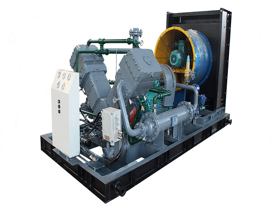
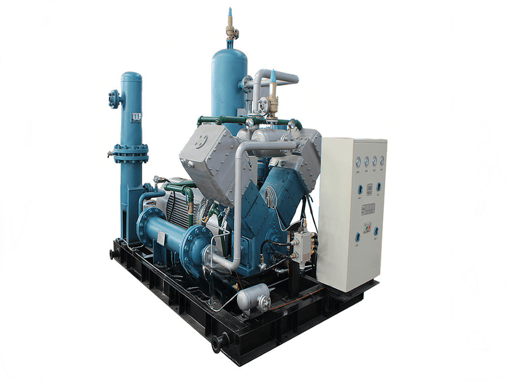
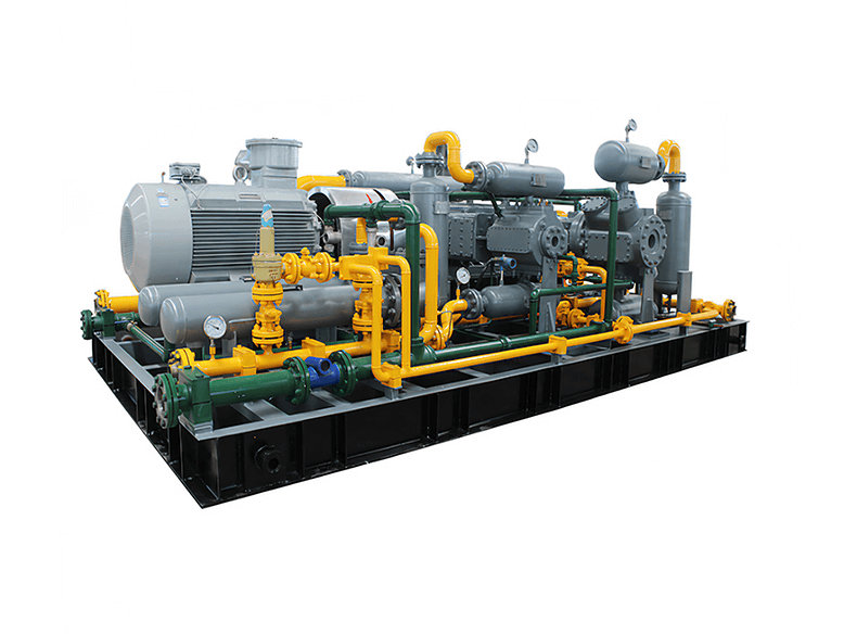
In the history of refrigeration technology, ammonia (NH₃, designated R717) occupies an irreplaceable position. In 1876, the German engineer Carl von Linde built the first ammonia compressor, ushering in a new era of mechanical refrigeration. Over the past nearly 150 years, ammonia refrigeration systems have continued to play a critical role in industrial refrigeration, food freezing, petrochemical processing, pharmaceutical manufacturing, and many other fields, owing to their superior thermodynamic performance and environmental compatibility.
The Four Core Components of the Ammonia Refrigeration Cycle
The ammonia vapor-compression refrigeration cycle consists of four fundamental thermodynamic processes, each corresponding to a key piece of equipment:
Evaporator: Low-pressure, low-temperature liquid ammonia absorbs heat from the medium being cooled within the evaporator, undergoing a phase change to vaporize into low-pressure, low-temperature superheated ammonia vapor, thereby producing the refrigeration effect. This process follows the mechanism of boiling heat transfer, with the evaporation temperature governed by the system operating pressure.

Compressor: Low-pressure, low-temperature ammonia vapor from the evaporator enters the compressor, where mechanical compression raises both its pressure and temperature significantly, converting it into high-pressure, high-temperature superheated ammonia vapor. The compression process may be approximated as an isentropic process, and its power consumption accounts for the major portion of the total system energy input.
Condenser: The high-pressure, high-temperature superheated ammonia vapor flows through the condenser, where it exchanges heat with cooling water or air. After releasing both sensible and latent heat, it condenses into high-pressure, ambient-temperature liquid ammonia. The condensing temperature is determined by the cooling medium temperature and the heat transfer conditions.
Throttling device (expansion valve): As the high-pressure, ambient-temperature liquid ammonia passes through the throttling element, it undergoes adiabatic flash evaporation, with a sharp pressure drop accompanied by a corresponding temperature reduction, becoming low-pressure, low-temperature wet vapor that re-enters the evaporator to begin the next cycle.
These four processes are sequentially interconnected to form a complete vapor-compression refrigeration cycle.
The Core Role of the Compressor
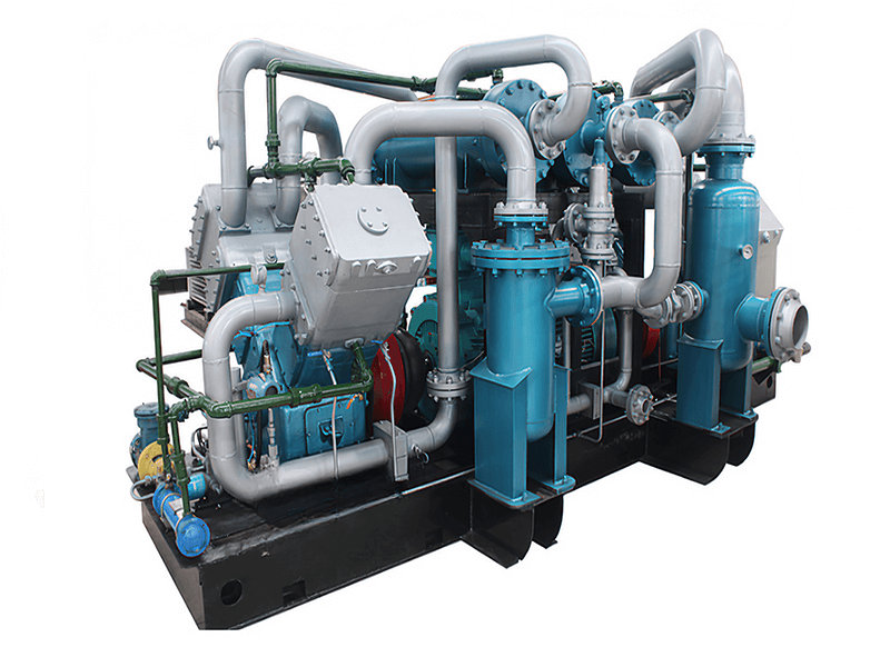
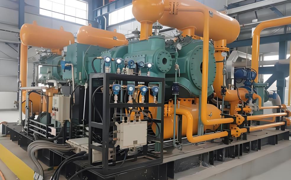
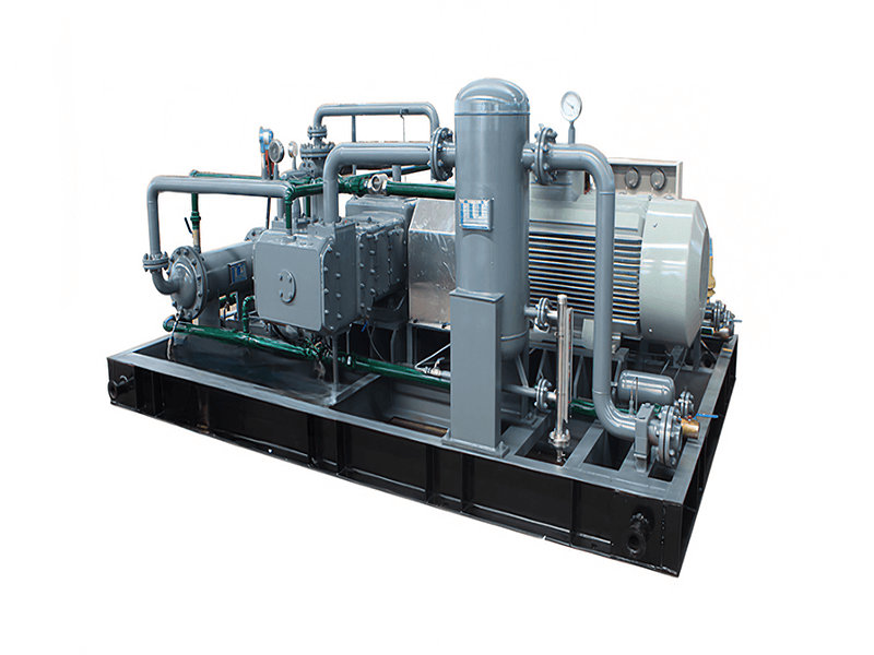
The compressor serves as the driving force of the refrigeration cycle and is often referred to as the "heart" of the system. Its core functions are twofold. First, it raises the low-pressure ammonia vapor from the evaporator to a pressure level sufficiently high to enable condensation at ambient temperature by the cooling medium. Without compression, the condensing temperature of ammonia vapor would remain below the ambient temperature, making it impossible for the condensation heat release to occur spontaneously. Second, the continuous operation of the compressor maintains the pressure differential between the high‑ and low‑pressure sides of the system, driving the ammonia refrigerant to circulate continuously through the piping network and thus achieve uninterrupted refrigeration. From an energy conversion perspective, the compressor transforms electrical energy into mechanical energy, which is subsequently converted into pressure energy and thermal energy of the ammonia vapor, ultimately accomplishing the purpose of refrigeration through heat and cold exchange.
Configuration of Practical Refrigeration Systems
Practical ammonia refrigeration systems in engineering are considerably more complex than the basic cycle. In addition to the four primary components, auxiliary equipment must be incorporated, including oil separators (to remove lubricating oil entrained in the compressor discharge), ammonia receivers (to store condensed liquid ammonia and regulate liquid supply), liquid separators (to prevent liquid carryover from the evaporator outlet into the compressor), and intercoolers (for interstage cooling in two-stage compression systems).
Taking a two-stage compression system as an example, the typical process flow is as follows: low-pressure ammonia vapor is compressed by the low-stage compressor, discharged into an oil separator, then routed to the intercooler for cooling, and subsequently enters the high-stage compressor for further compression. The high‑stage discharge gas is condensed into liquid ammonia in the condenser, stored in the receiver, throttled to the low-pressure level, and supplied to the evaporator for refrigeration. The appropriate configuration of these auxiliary devices effectively enhances the system's economic efficiency, operational reliability, and safety.
The working principle of the ammonia compressor is grounded in classical thermodynamics. The seemingly straightforward four‑step cycle in fact embodies sophisticated thermodynamic design and engineering considerations. It is the continuous operation of the compressor that enables ammonia, a natural refrigerant, to deliver outstanding refrigeration performance across modern industrial applications.