The selection of a Wellhead Gas Compressor directly impacts the economic viability of gas field development, equipment operational reliability, and onsite safety. An inappropriate selection can lead not only to wasted investment or constrained production capacity, but also to frequent shutdowns, equipment damage, and even safety incidents. Therefore, before finalizing a compressor unit configuration, it is essential to systematically review key parameters and make rational decisions based on specific well conditions.
1. Data Preparation Prior to Selection
The starting point of any selection exercise is the collection of complete and reliable field data. Three core dimensions are indispensable:
1.1 Gas Composition Analysis
A representative gas sample analysis report must be obtained, with particular attention to the following:
Methane (CH₄) content determines the heating value and compressibility of the gas.
Non‑hydrocarbon components such as nitrogen (N₂) and carbon dioxide (CO₂), which reduce volumetric efficiency.
Hydrogen sulfide (H₂S) contentdirectly affects the material's resistance to stress corrosion cracking.
Water content and water dew pointdetermine whether upstream dehydration is required.
In addition, the presence of condensate oil or solid particles (e.g., fracturing sand, rust) should be assessed, as these can influence compressor cylinder lubrication and valve life.
1.2 Pressure and Flow Rate Parameters
Inlet pressure: expected wellhead pressure range (minimum, normal, maximum) for the current year and the following three years. Typical values: low‑pressure wells 0.2–0.8 MPa, medium‑pressure wells 1.0–3.0 MPa.
Discharge pressure: required inlet pressure of the downstream pipeline network or processing facility, typically 1.2–6.0 MPa; for CNG filling applications, this can reach 20–25 MPa.
Flow rate requirement: determined based on the absolute open flow (AOF) potential of the gas well and a reasonable production drawdown. Common units: Nm³/d or 10⁴ m³/d. Attention must be paid to conversion between standard and actual conditions.
If accurate values for the above parameters cannot be obtained, reference should be made to production data from adjacent wells or reservoir engineering forecasts, and a certain fluctuation range should be reserved.

2. Compressor Type Comparison & Selection Recommendations
Different well conditions impose significantly different performance requirements on compressors. The most suitable machine type must be selected according to the specific operating conditions.
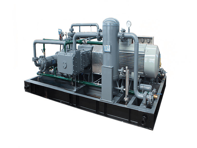
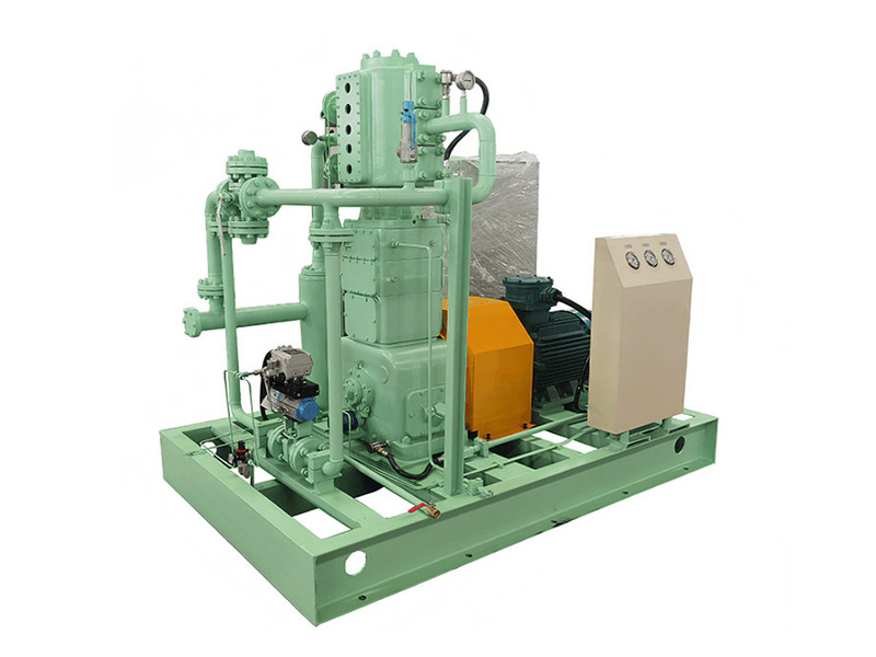
Low output, lowpressure wells: Typical characteristics – gas production <1×10⁴ Nm³/d, inlet pressure 0.1–0.5 MPa. Recommended type: small reciprocating compressor (V‑ or W‑configuration). Reason: reciprocating compressors offer good high‑pressure‑ratio capability, high efficiency, and can tolerate intermittent operation with low sensitivity to output fluctuations.
High‑output, low‑pressure wells: Gas production >5×10⁴ Nm³/d, inlet pressure 0.3–0.8 MPa. Options: multi‑stage reciprocating compressor or screw compressor. Screw compressors have better tolerance to liquids, but note that their maximum discharge pressure is typically limited to ≤4.0 MPa, making them unsuitable for high‑pressure‑ratio applications.
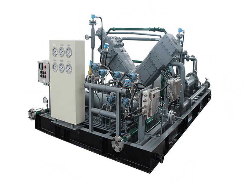
Direct pressurization of high‑pressure wells: Wellhead pressure already 5–15 MPa, target discharge pressure above 20 MPa. Recommended type: two‑stage or three‑stage reciprocating compressor. The reciprocating design achieves high compression ratios and reliable high‑pressure sealing, meeting the requirements for CNG filling or high‑pressure gas injection.
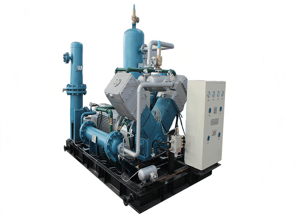
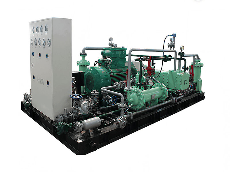
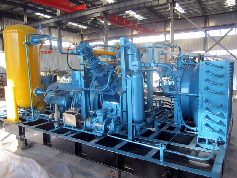
Shale gas wells:Production characteristics – rapid pressure decline, high liquid production, and gas often carries solid particles such as fracturing sand. Optimal configuration: skid‑mounted reciprocating compressor, equipped with a high‑efficiency gas‑liquid separator upstream of the compressor inlet. Reciprocating compressors have good resistance to liquid slugging, and the upstream separator protects valve assemblies and cylinders.
Stable gas source at gathering station: Small inlet pressure fluctuation, large flow rate (typically >20×10⁴ Nm³/d). Options: centrifugal compressor or large screw compressor. Centrifugal compressors offer smooth continuous operation and a small footprint, but are highly sensitive to operating condition variations. They are not suitable for wellhead follow‑up pressurization where pressure declines rapidly, and should only be used as pipeline booster equipment.
Special note: Centrifugal compressors should not be used directly for wellhead follow‑up pressure boosting, as they would frequently enter the surge region, leading to blade damage.
3. Driver Selection
Electric motor drive vs. gas engine drive
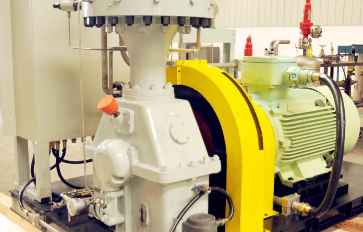
Electric motor drive: High efficiency (≈95% at full load), simple maintenance, zero on‑site emissions. Suitable for areas with reliable grid access. In explosive atmospheres, high‑voltage explosion‑proof motors (Ex d IIB T4) can be used. However, voltage drop during start‑up of large‑power motors must be considered.
Gas engine drive: Can use wellhead gas as fuel, suitable for remote well sites without grid power or with insufficient power capacity. Disadvantages: requires a separate cooling system, shorter maintenance intervals (oil changes, spark plugs). Waste heat from the exhaust can be recovered for tracing or heating.
Solutions for remote areas without grid power
If the well site is more than 5 km from the grid and the load is relatively small, the following combinations can be considered:
Gas engine driven compressor + small generator for instrumentation and lighting.
Solar photovoltaic + battery bank to power RTUs and solenoid valves.
For extremely low‑gas‑rate wells, a pneumatic booster pump (no electrical demand) can be used.
An economic comparison is necessary: the cost of building a dedicated power line is often higher than that of a gas‑engine‑driven solution.
4. Material & Protection Rating Considerations
Explosion protection requirements
Natural gas falls into Group IIA or IIB explosive gas categories. Well sites are typically Zone 2 or Zone 1 hazardous areas. The complete compressor unit must have an explosion protection certificate. Motors, instruments, and junction boxes shall comply with GB 3836 or ATEX standards. The control panel should be placed in a pressurized, ventilated non‑hazardous area or be of a flameproof design.
Corrosion‑resistant material selection
H₂Scontaining environment (>50 ppm): Cylinders, valve plates, and fasteners must meet NACE MR0175/ISO 15156, using sulfide‑stress‑crackingresistant materials such as 17‑4PH stainless steel (with appropriate heat treatment) or nickel‑based alloy coatings.
CO₂containing environment: Chromium‑plated piston rods and stainless steel valve assemblies can be used.
Wet natural gas with Cl⁻ ions: Avoid austenitic stainless steel parts susceptible to stress corrosion cracking. Duplex stainless steel or corrosion‑resistant alloys are recommended.
Depending on the dew point temperature of the gas stream, the compressor inlet should be equipped with heat tracing or methanol injection to prevent freezing.
5. Common Selection Mistakes & Avoidance Tips
Mistake 1: Excessive or insufficient margin
Some users, seeking a "safety margin", specify a flow margin >50%. This forces the compressor to run at low load for long periods, leading to valve flutter, oil carbon deposits, and excessively low discharge temperatures. Conversely, insufficient margin forces overspeed operation and accelerates wear. Reasonable approach: flow margin 10–20%, pressure margin 5–10%.
Mistake 2: Ignoring inlet temperature fluctuations
Summer wellhead temperatures can exceed 50 °C, while winter temperatures may drop to –20 °C. If the compressor is selected based on normal temperature, the actual inlet specific volume will be higher at high temperatures, reducing mass flow. At low temperatures, the inlet density increases, potentially overloading the motor or engine. The inlet temperature range must be specified during selection, and compressor performance curves should be verified at extreme temperatures.
Other common mistakes include:
Neglecting the gas/liquid ratio, leading to liquid slugging damage.
Ignoring the match between pipe diameter and compressor nozzle size, resulting in excessive pressure drop.
Failing to reserve remote control interfaces, increasing the difficulty of future digital retrofits.
6. Summary
Proper selection of a wellhead gas compressor should be based on accurate gas source data, a rational classification of well conditions, a matching driver type, and a rigorous material and explosion protection system. Avoiding typical errors such as inappropriate margins and neglect of temperature fluctuations significantly reduces the total cost of ownership. It is recommended to commission a professional compressor manufacturer to perform a condition simulation before procurement, and to retain on‑site dynamic adjustment capability. Only then will the compressor unit become a reliable source of power for gas field production rather than a hidden source of frequent shutdowns.